Well Water & Pressure Booster Tanks
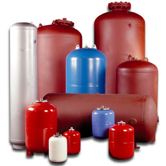
 There are several different functions that a hydropneumatic tank can perform. In a booster pump application, it can provide water to the system during periods of a no flow shutdown of the booster pump or it can provide water to replace leak loads. In a well water application, it can provide the desired volume of water required between the pump shut down pressure and the pump turn on pressure.
In a sprinkler or irrigation pump application, the tank may provide a cushion to maintain necessary pressure so the jockey pump will not short cycle. In any case, the amount of water that the tank will be required to supply to the system during any given cycle is called the drawdown. Drawdown must first be determined to properly size the hydropneumatic tank.
What are Hydropneumatic Tanks?
Hydropneumatic tanks are ASME and non-ASME vessels that hold water and air under pressure. In order to provide efficient water supply, hydropneumatic tanks regulate system pressures to quickly meet system demand. The compressed air creates a cushion that can absorb or apply pressure as needed. Air that is reabsorbed into the system water is sometimes replenished with the addition of a small air compressor. Large hydropneumatic tanks with volumes of 2,000 gallons or more are usually installed horizontally. Normal operating pressure is in the range of 60 to 75 PSI, so most hydropneumatic tanks are rated to 100 PSI.
Divider
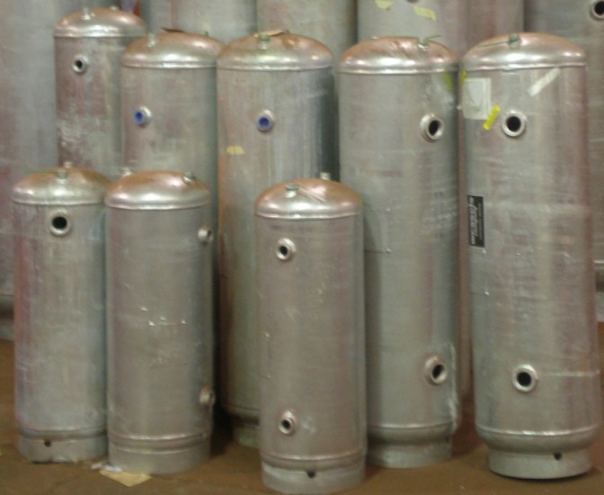
 Galvanized Compression Tanks (ASME)
Compression tanks are designed to absorb the expansion forces and control the pressure in heating or cooling systems. This tank is the oldest style that has been used in these systems. It works well when the air is controlled and kept in the tank and not in the system.
Divider
 Bladder Tanks (ASME / Non-ASME)
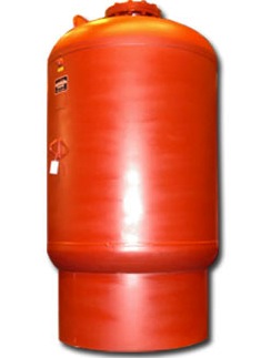
Bladder tanks are required in a closed loop heating or chilled water HVAC system to absorb the expanding fluid and limit the pressure within a heating or cooling system. A properly sized expansion or compression tank will accommodate the expansion of the system fluid during the heating or cooling cycle without allowing the system to exceed the critical pressure limits of the system.
Divider
 Diaphragm Tanks (ASME / Non-ASME)
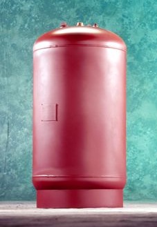
The diaphragm tank has been developed to allow the systems air cushion to be separated from the systems water. No waterlogging of the tank can occur as the air is held between the tank wall and the outside of a bladder placed inside the tank, while the system water is contained inside the bladder. This changes the system to an air elimination system, as any air extracted from the system water is passed out of the system into the atmosphere.

