
Data centers are in a full-tilt gold rush and the winners are the ones “tanking” advantage of smarter HVAC design. With nonstop thermal loads and tight efficiency targets, system stability matters more than ever. Wessels TES thermal energy storage tanks allow operators to shift cooling to off-peak hours, smooth out fluctuations, and gain valuable capacity without oversizing chillers. When paired with Wessels buffer tanks and high-pressure bladder expansion tanks, chilled water loops maintain steady performance and protect uptime.
Reliability is equally critical in mission-critical environments. Wessels SS-AP stainless steel air purgers remove damaging entrained air that can disrupt pumps and reduce overall performance. Stainless construction options throughout the product line support glycol and strict water quality requirements in modern data center designs. From TES tanks that shave peaks to SS-AP air management that keeps systems clean and consistent, Wessels helps data centers turn HVAC infrastructure into a competitive advantage.
Thermal Energy Storage Tanks
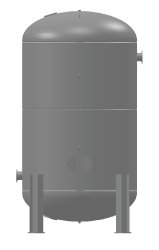
Wessels TES Thermal Energy Storage Tanks are designed to store thermal energy for cooling data centers, renewable energy applications, loss of power, or delivery during off-peak hours. The tanks feature dual inner-screen WesPro Super Baffle Systems to stratify and reduce the thermal mixing zone (thermocline), increasing the delivery efficiency of hot or chilled water.
Low water volume systems require additional “buffer energy” capacity to eliminate problems such as excessive equipment cycling, poor temperature control, and erratic system operation. The TES Tank adds the necessary volume to “buffer” the system volume.

Air Purgers
In-line Air Purgers are used for commercial and industrial hydronic systems, to effectively control and eliminate entrained air.
The SS-AP Series air purgers:
- Rated to 450°F and 150 PSI
- Designed with an embossed flow indicator arrow for proper installation.

More →

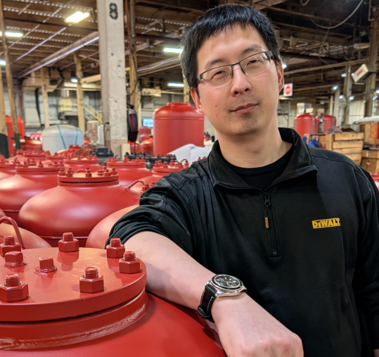 Wessels Company welcomes Landon Yan to our engineering team! He has been a design engineer with us since April of this year and he says he enjoys the challenge that the position gives him. Landon is a Purdue University graduate, so he will fit right in with the long list of Purdue alumni at Wessels. When he’s not in the office, Landon is a budding YouTuber and Twitch streamer. He spends his spare time practicing martial arts, sketching and playing the guitar and accordion. One of his dislikes is “being the new guy”, but we’re sure he will quickly fit in and become an integral part of the Wessels team. Please join us in welcoming Landon!

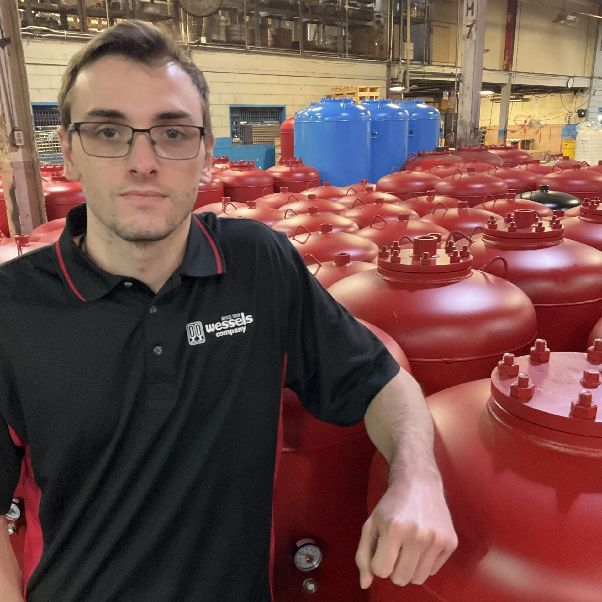 Please welcome a new member to our Engineering department: Zach Pokrzywinski. Zach joined the Wessels family in December of 2025 as a design engineer and says his favorite thing about the new job is being able to create tanks with great people. In his spare time, he enjoys playing video games, playing and watching sports, and working out. He also loves rooting for the Pittsburgh Steelers.


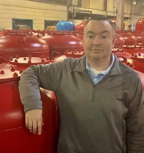


 Wessels Company is excited to welcome Scott Dewey back to our engineering team as Senior Manufacturing Engineer. Scott previously spent a year and a half with Wessels before relocating across the country and has now returned to Indiana to rejoin the company. A graduate of Indiana State University with a bachelor’s degree in engineering, Scott brings valuable experience and a strong commitment to manufacturing excellence. Outside of work, he enjoys home renovation projects, spending time with his family and dogs, and being outdoors. Scott is also a proud stage 4 cancer survivor. We’re happy to have him back with us!
 We are pleased to welcome Michele Curtis as the newest member of the Wessels team, joining our inventory department at the start of September. Michele brings a strong educational background from Ivy Tech, where she studied business and mathematics, along with several years of managerial experience in manufacturing at a snack company. Outside of work, she enjoys outdoor activities, weekend road trips, and fishing with her husband, as well as spending time with her granddaughter and watching football and baseball. An interesting note about Michele is that she is left-handed. Her colleagues, who share an office with her, appreciate her positive demeanor and ability to uplift the workplace atmosphere.