Understanding Expansion Factor

Expansion factor is defined as the fractional change of the volume of a substance from a change in its temperature. Simply said, as a substance temperature increases, its volume increases. This is important when determining the amount of fluid that will expand in a hydronic system and subsequently the expansion tank needed to accommodate this increase.
We will look at fluid expansion with an end towards what is considered the accurate estimation as documented in the ASHRAE Fundamentals Handbook. The equation is fundamentally:
Net expansion = gross expansion of fluid minus expansion of piping and components
This is typically expressed as a fraction that is then multiplied by the total system volume of the hydronic system to calculate the expanded fluid. To that end, the gross expansion is the difference in specific volumes at two temperatures divided by the starting (lower temperature) specific volume.
Gross Expansion Factor of Fluid = ((v2-v1))/v1 = v2/v1-1
Where:
v1: specific volume of the fluid at temperature t1 (higher temperature)
v2: specific volume of the fluid at temperature t2 (lower temperature)
The expansion of the piping and components can be cumbersome to calculate because different component materials (boilers/chillers, air separators, heat exchangers, etc.) may be at potentially different temperatures, so an estimation is needed to be made. The traditional approach is to make all components materials homogeneous with the system piping and all at the same stop/start temperatures. The formula for calculating the change in volume of a solid or liquid due to thermal expansion is:
Expansion Factor of Piping and Components = β(t2-t1)
Where:
β: coefficient of the ratio of volumetric expansion of the piping material ((in3/in3)oF) The coefficient can be estimated:
β≅3α
Making the equation:
Expansion Factor of Piping and Components = 3α(t2-t1)
Where:
α: Coefficient of the ratio of linear expansion of the piping material (in/inoF)
For the exacting-minded, the actual equation for the growth factor of the expansion of piping and components is:
Expansion Factor of Piping and Components = (α(t2-t1)+1)^3-1
This is the integration of the circumferential and linear growth of a hollow cylinder (pipe). The approximation of 3α(t2-t1) follows the equation with less than 1 percent difference over the temperature range from -100oF to 350oF, which makes the 3α(t2-t1) a more convenient equation estimation.
Linear expansion coefficients (α) for common materials are shown in the following table:
|
Material |
α (in./in./oF) |
|
Ductile Iron |
6.20E-06 |
|
PVC |
3.00E-05 |
|
Cast Iron |
6.11E-06 |
|
Steel |
6.67E-06 |
|
HDPE |
8.00E-05 |
|
Concrete |
5.50E-06 |
|
Copper |
9.44E-06 |
And yes, this paper uses English units because who could argue with the exact science behind the inch, foot, yard, and pound and Fahrenheit? USA, Liberia, and Myanmar can’t all be wrong! Even the United Kingdom abandoned and switched to Celsius decades ago. Oh well, go ‘Merica!

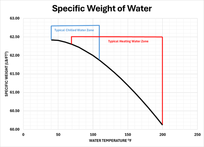
It is important to review the specific weight of water and discuss the differences of heating and chilled water systems. The chart shows the profile of specific weight and the typical chilled water and typical heating system zones. The fact that water density in a heating water system decreases at a considerably greater rate than in a chilled water system, shows that a single linear approximation equation is not a n accurate option. In fact, as will be shown, the piping can expand greater than the water at lower temperatures.

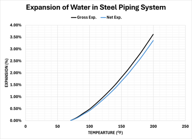
The net expansion of water starting at 70oF in a hydronic heating system as influenced by the piping material is shown in the following chart for steel piping:

Charts can be deceiving in assessing the influence of the component expansion. This impact of steel pipe expansion on the net expansion of the water in the piping system is shown in the following table.
|
Heating System |
|||
|
mp (oF) |
Gross Exp. |
Net Exp. |
% Reduction |
|
70 |
0.00% |
0.00% |
– |
|
80 |
0.13% |
0.11% |
15.55% |
|
90 |
0.31% |
0.27% |
13.08% |
|
100 |
0.48% |
0.42% |
12.40% |
|
110 |
0.71% |
0.63% |
11.25% |
|
120 |
0.96% |
0.86% |
10.46% |
|
130 |
1.22% |
1.10% |
9.85% |
|
140 |
1.50% |
1.36% |
9.34% |
|
150 |
1.81% |
1.65% |
8.82% |
|
160 |
2.13% |
1.95% |
8.45% |
|
170 |
2.48% |
2.28% |
8.05% |
|
180 |
2.84% |
2.62% |
7.75% |
|
190 |
3.23% |
2.99% |
7.43% |
|
200 |
3.63% |
3.37% |
7.17% |
This reveals a dramatic impact on the expansion of the water in the heating system. Employing the same methodology to the chilled water system starting at 40oF, the impact of the steel piping has an even greater influence on the net expansion.
|
Chilled Water System |
|||
|
Temp (oF) |
Gross Exp. |
Net Exp. |
% Reduction |
|
40 |
0.00% |
0.00% |
– |
|
50 |
0.02% |
0.00% |
-24.82% |
|
60 |
0.10% |
0.06% |
58.43% |
|
70 |
0.19% |
0.13% |
68.85% |
|
80 |
0.32% |
0.24% |
75.11% |
|
90 |
0.50% |
0.40% |
79.96% |
|
100 |
0.68% |
0.56% |
82.29% |
|
110 |
0.91% |
0.77% |
84.54% |
This shows that at times the lower temperature piping expands faster that the water.
Propylene Glycol
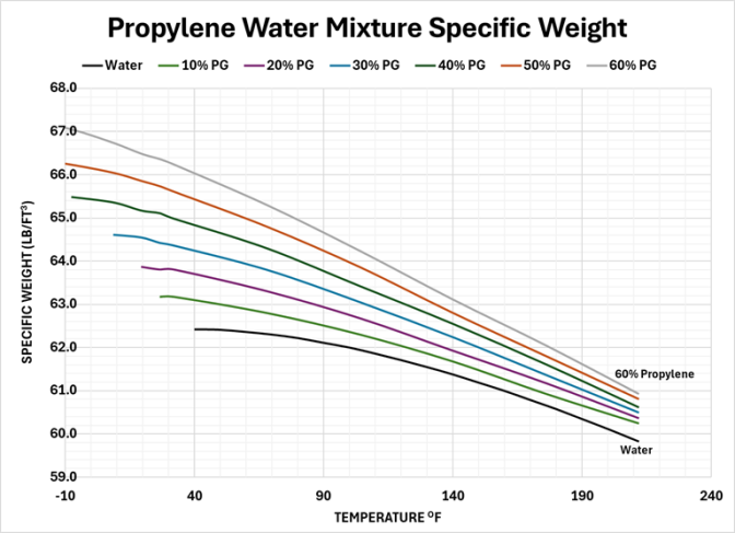
The mixture of propylene glycol has the effect of increasing specific weight and increasing the slope of the rate of change.

The resulting net expansion of various propylene concentrations are shown for typical heating and chilled hydronic loops. The chart for heating shows the expansion factor with 70oF as the starting temperature.
|
Net Expansion Heating System |
|||||||
|
Temp (oF) |
Water |
10%PG |
20%PG |
30%PG |
40%PG |
50%PG |
60%PG |
|
70 |
0.00% |
0.00% |
0.00% |
0.00% |
0.00% |
0.00% |
0.00% |
|
80 |
0.11% |
0.22% |
0.27% |
0.33% |
0.38% |
0.40% |
0.45% |
|
90 |
0.27% |
0.44% |
0.55% |
0.66% |
0.76% |
0.81% |
0.91% |
|
100 |
0.42% |
0.67% |
0.83% |
0.99% |
1.15% |
1.22% |
1.37% |
|
110 |
0.63% |
0.93% |
1.14% |
1.34% |
1.53% |
1.67% |
1.86% |
|
120 |
0.86% |
1.21% |
1.48% |
1.70% |
1.93% |
2.14% |
2.36% |
|
130 |
1.10% |
1.49% |
1.82% |
2.07% |
2.32% |
2.62% |
2.86% |
|
140 |
1.36% |
1.78% |
2.16% |
2.44% |
2.72% |
3.10% |
3.37% |
|
150 |
1.65% |
2.12% |
2.51% |
2.84% |
3.15% |
3.56% |
3.85% |
|
160 |
1.95% |
2.47% |
2.85% |
3.25% |
3.58% |
4.02% |
4.34% |
|
170 |
2.28% |
2.82% |
3.20% |
3.65% |
4.01% |
4.48% |
4.84% |
|
180 |
2.62% |
3.16% |
3.57% |
4.06% |
4.47% |
4.95% |
5.35% |
|
190 |
2.99% |
3.48% |
3.95% |
4.48% |
4.94% |
5.43% |
5.88% |
|
200 |
3.37% |
3.81% |
4.34% |
4.90% |
5.42% |
5.91% |
6.42% |
The chart for chilled hydronic systems shows the net expansion with the lowest temperature that concentration of propylene glycol is anticipated to start expanding. For example, 40% propylene glycol starts expanding from -10oF (its lowest anticipated temperature).
|
Net Expansion Chilled System |
|||||||
|
Temp (oF) |
Water |
10%PG |
20%PG |
30%PG |
40%PG |
50%PG |
60%PG |
|
-50 |
|
|
|
|
|
|
0.00% |
|
-40 |
|
|
|
|
|
|
0.08% |
|
-30 |
|
|
|
|
|
0.00% |
0.16% |
|
-20 |
|
|
|
|
|
0.11% |
0.32% |
|
-10 |
|
|
|
|
0.00% |
0.26% |
0.51% |
|
0 |
|
|
|
0.00% |
0.09% |
0.42% |
0.78% |
|
10 |
|
|
0.00% |
0.01% |
0.23% |
0.60% |
1.08% |
|
20 |
|
|
0.01% |
0.11% |
0.49% |
0.87% |
1.42% |
|
30 |
|
0.00% |
0.10% |
0.35% |
0.70% |
1.17% |
1.72% |
|
40 |
0.00% |
0.13% |
0.27% |
0.58% |
1.01% |
1.52% |
2.11% |
|
50 |
0.02% |
0.30% |
0.49% |
0.83% |
1.30% |
1.87% |
2.52% |
|
60 |
0.10% |
0.46% |
0.71% |
1.07% |
1.60% |
2.22% |
2.92% |
|
70 |
0.19% |
0.64% |
0.94% |
1.34% |
1.92% |
2.59% |
3.34% |
|
80 |
0.32% |
0.86% |
1.22% |
1.67% |
2.31% |
3.00% |
3.81% |
|
90 |
0.50% |
1.09% |
1.50% |
2.00% |
2.70% |
3.42% |
4.29% |
|
100 |
0.68% |
1.31% |
1.78% |
2.34% |
3.09% |
3.84% |
4.76% |
|
110 |
0.91% |
1.57% |
2.10% |
2.70% |
3.49% |
4.30% |
5.26% |
There are many aspects of expansion that can be further explored as to their significance:
- Is the component and piping expansion coefficient truly linear?
- Should the final temperature of a heating loop and the starting temperatures of a chilled hydronic loop be better represented as (ts+tr)/2? Where ts = supply temperature and tr = return temperature?
The entire specific volumes are included at the final pages of this paper and can be used to develop a simple spreadsheet to use lookup functions and piping material inputs to accurately calculate the expansion factor for any system input (between -50oF and 240oF). For other heat transfer and antifreeze fluids, simply add these to your spreadsheet for future reference.
Sam Fuller
Technical Engineer
Wessels Company
